Impedance circuit
Attachment not found
For part b of this question is this the correct circuit diagram?
If not can someone point me towards the correct setup as for me the wording of the question isnt clear...
Posted from TSR Mobile
Original post by Goods
For part b of this question is this the correct circuit diagram?

If not can someone point me towards the correct setup as for me the wording of the question isnt clear...
Posted from TSR Mobile
Attachment not found
For part b of this question is this the correct circuit diagram?
If not can someone point me towards the correct setup as for me the wording of the question isnt clear...
Posted from TSR Mobile
Your file attachment is not loading. Can you repost please? Ta.
Original post by uberteknik
Hi.
Your file attachment is not loading. Can you repost please? Ta.
Your file attachment is not loading. Can you repost please? Ta.
Posted from TSR Mobile
Original post by Goods
No worries.
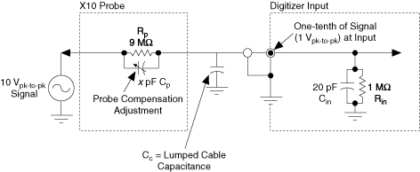
C3 represents the lumped cable capacitance which the question says Is between the input to the oscilloscope and ground.
Therefore C3 should be parallel with the oscilloscope input impedance.
(Values in the attached diagram are not quite the same as your question).

(edited 9 years ago)
Original post by uberteknik
so removing the text is this the circuit in question? where v2 is the voltage across only the right hand RC parallel section?
Original post by Goods
so removing the text is this the circuit in question? where v2 is the voltage across only the right hand RC parallel section?
You got it!

Original post by Goods
so removing the text is this the circuit in question? where v2 is the voltage across only the right hand RC parallel section?
The connecting cable is co-axial: a single test-signal conductor sheathed in a braided shield (Faraday cage) connected to ground.
The shield is isolated from the signal conductor by a rigid pvc spacer which has an air core (dielectric) to aid mechanical flexibility.
In other words, the connecting cable forms a capacitor whose total capacitance is a function of the dielectric properties, cable length and spacing.
(edited 9 years ago)
Original post by uberteknik
You got it! 

I followed that arrangement and arrived at this, but from here I have no idea how to work out c1 such that v2/v1 is independent of w. Ive checked a few times and get the same fraction for v2/v1....
Posted from TSR Mobile
Quick Reply
Related discussions
- Impedance
- electrical schematics and analyzing signals
- RLC circuit
- HNC electrical engineering
- physics alevel edexcel circuit question
- Capacitor Question (PHYS)
- Circuits Question
- ac theory question
- Physics GCSE question
- resistance in a parallel circuit
- Use a simulator to produce a resonance curve between 800 Hz and 4.5 kH
- Isaac Physics.
- Superposition theorem problem
- NEA game ideas
- HNC science
- Circuit laundry is so annoying and i just lost some money
- Resistance of the LDR
- Confusing Capacitor question
- How does the variable resistor circuit provide a larger current?
- Experience of using Circuit Laundry at Uni of Notts?

