physics questions
hi ive got a few questions that ive attached one of them is split in 2, its just a few stuff thats been confusing me. thanks. the first 2 pictures are part 1 and part2 respectively of the question. the rest are individual questions.
(edited 8 years ago)
Original post by nmjasdk
hi ive got a few questions that ive attached one of them is split in 2, its just a few stuff thats been confusing me. thanks. the first 2 pictures are part 1 and part2 respectively of the question. the rest are individual questions.
Drawing from terminals A to B: place the 100 ohms resistor in series with the ammeter then in series with the LED anode with the LED cathode connected to terminal B. (NB, these series components can be placed in any order between A and B, but the LED must be connected anode towards the battery +ve terminal and cathode towards the -ve terminal.)
Place the voltmeter in parallel with this series combination directly across terminals A and B.
This is the closest schematic I could find. All components are in the correct places except the variable resistor is missing which should be placed between the battery +ve terminal and the voltmeter/ammeter junction:

Original post by nmjasdk
hi ive got a few questions that ive attached one of them is split in 2, its just a few stuff thats been confusing me. thanks. the first 2 pictures are part 1 and part2 respectively of the question. the rest are individual questions.
The experiment requires the p.d. across the LED to be varied.
The best test circuit will allow the widest possible range of p.d. to be developed across the (LED + 100) ohms series resistor combination from 0V up to the supply maximum voltage.
Fig 4.3 achieves this by the variable resistor arrangement which produces a continuously variable test voltage output between 0V up to the 6V supply voltage. (A range of 6V).
The arrangement of fig 4.2. will produce a limited test voltage range between:
Unparseable latex formula:
V_{min} = V_{supply}\big(\frac{100}{(100 + 10)}\big) = 5.45 \mathrom{V}
and
i.e. a range of 0.55V
(edited 8 years ago)
Original post by nmjasdk
hi ive got a few questions that ive attached one of them is split in 2, its just a few stuff thats been confusing me. thanks. the first 2 pictures are part 1 and part2 respectively of the question. the rest are individual questions.
Seems a bit churlish. Perhaps your teacher thought they were a bit too untidy and not accurate enough?
The BS3939 (internationally recognised) symbols are:

2nd part:
It looks similar to the parallel equation for two resistors, but it's not the same so don't confuse the two.
The voltage developed across the potential divider combination is derived from ohms law:
and because it's a series combination, the current through all components must be the same:
The voltage developed across any series resistor (and in our case the 750 ohm resistor) is:
therefore after substitution:
which rearranges to
(edited 8 years ago)
Original post by uberteknik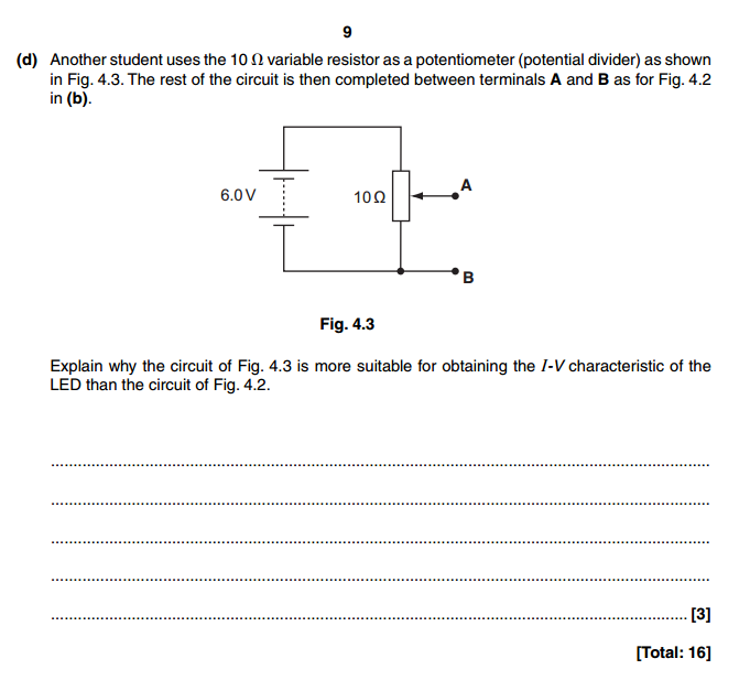
The experiment requires the p.d. across the LED to be varied.
The best test circuit will allow the widest possible range of p.d. to be developed across the (LED + 100) ohms series resistor combination from 0V up to the supply maximum voltage.
Fig 4.3 achieves this by the variable resistor arrangement which produces a continuously variable test voltage output between 0V up to the 6V supply voltage. (A range of 6V).
The arrangement of fig 4.2. will produce a limited test voltage range between:
and
i.e. a range of 0.55V
The experiment requires the p.d. across the LED to be varied.
The best test circuit will allow the widest possible range of p.d. to be developed across the (LED + 100) ohms series resistor combination from 0V up to the supply maximum voltage.
Fig 4.3 achieves this by the variable resistor arrangement which produces a continuously variable test voltage output between 0V up to the 6V supply voltage. (A range of 6V).
The arrangement of fig 4.2. will produce a limited test voltage range between:
Unparseable latex formula:
V_{min} = V_{supply}\big(\frac{100}{(100 + 10)}\big) = 5.45 \mathrom{V}
and
i.e. a range of 0.55V
i get why the fig 4.2 has a range of 055v but i dont understand how the fig 4.3 arrangement can give 0v, to be honest i dont even know what going on in that arrangement because i dont understand why theat variable resistor now has a arrow going onto it what does that even mean? its also called a potential divider in fig 4.3 but it alreaydy was a potential divider in fig 4.3 anyway.
Original post by uberteknik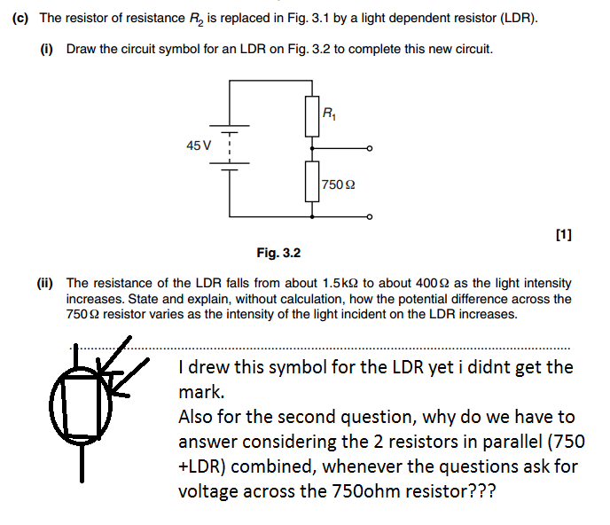
Seems a bit churlish. Perhaps your teacher thought they were a bit too untidy and not accurate enough?
The BS3939 (internationally recognised) symbols are:
2nd part:
It looks similar to the parallel equation for two resistors, but it's not the same so don't confuse the two.
The voltage developed across the potential divider combination is derived from ohms law:
and because it's a series combination, the current through all components must be the same:
The voltage developed across any series resistor (and in our case the 750 ohm resistor) is:
therefore after substitution:
which rearranges to
what worrying my about the symbol i drew is that was the symbol i drew on my actual exam test and i didnt get the mark so it wasnt my teacher it was an actual examiner that thought the symbol was wrong.
anyway also wanted to say thanks for the detailed answers honestly appreciate it.
Quick Reply
Related discussions
- GCSE Exam Discussions 2024
- A level physics without maths
- What online resources can I use to guarantee I get an A in A-Level AQA Physics?
- Is Physics A-Level even THAT hard?
- Isaac physics quantum mechanics primer difficulty level
- What are these a levels and their courses like?
- Senior Physics Challenge Isaac Physics
- Taking a gap year to retake a levels, tips for getting A/A*?
- tough practice questions for a level science
- A-Level Physics
- A-level Physics Study Group 2022-2023
- Which A level is harder physics or further maths?
- Tips for A*s?
- What is Applications that relate to the field of applied physics?
- Where to find practise questions?
- tips and any advice to do well in a physics assessment (triple)
- A-level Physics Study Group 2023-2024
- Tutoring opportunities- A level/GCSE
- A level physics help
- Need help on what to do to improve on my a levels!
Latest
Last reply 3 minutes ago
British Council English Language Assistants 2024/2025Last reply 5 minutes ago
OCR A-level Religious Studies Paper 3 (Christianity) - 20th June 2024 [Exam Chat]Last reply 6 minutes ago
University of Nottingham, For EconomicsLast reply 8 minutes ago
Official London School of Economics and Political Science 2024 Applicant ThreadLast reply 10 minutes ago
Goldmansachs Degree Apprenticeship 2024Last reply 12 minutes ago
Help with preparing for criminal pupillage advocacy exercise?Last reply 14 minutes ago
Official UCL Offer Holders Thread for 2024 entryLast reply 15 minutes ago
Why is the political left now censorious and authoritarian??Last reply 15 minutes ago
Edexcel A-level Spanish Paper 2 (9SP0 02) - 17th June 2024 [Exam Chat]Last reply 19 minutes ago
About to finish LearnDirect Access to HE (Psychology & Criminology / Social Sciences)


