AS Physics Electrical Circuit Help
Original post by Jpw1097
Could somebody please explain part (ii) please?
What don't you understand? It's usually helpful if you say what you've already done for the question.
Original post by lerjj
What don't you understand? It's usually helpful if you say what you've already done for the question.
Well, I've already stated that as current increases, voltage decreases due to resistance decreases.
But the mark scheme says that when V is large, R is large which I understand, but it also says that V=e.m.f when R is infinite. I don't understand how that has come about
Original post by Jpw1097
Well, I've already stated that as current increases, voltage decreases due to resistance decreases.
But the mark scheme says that when V is large, R is large which I understand, but it also says that V=e.m.f when R is infinite. I don't understand how that has come about
But the mark scheme says that when V is large, R is large which I understand, but it also says that V=e.m.f when R is infinite. I don't understand how that has come about
Ok, so the situation is basically a potential divider and the voltage is being split between the variable resistor and the internal resistance of the cell.
What happens to how the voltage splits when you change the resistance of the variable resistor?
Original post by lerjj
Ok, so the situation is basically a potential divider and the voltage is being split between the variable resistor and the internal resistance of the cell.
What happens to how the voltage splits when you change the resistance of the variable resistor?
What happens to how the voltage splits when you change the resistance of the variable resistor?
I understand that, but it specifically states that V is also the terminal p.d.
Original post by Jpw1097
I understand that, but it specifically states that V is also the terminal p.d.
It is, the only resistance you've got connected is the variable resistor, hence the resistance across it must be the terminal p.d.
That's not the same as the emf, which is a little larger because of the voltage drop due to the internal resistance. As you make the variable resistance go to infinity, the current goes to zero and the lost volts from the internal resistance also goes to zero- making the terminal p.d. equal the emf.
Does that make sense?
Original post by lerjj
It is, the only resistance you've got connected is the variable resistor, hence the resistance across it must be the terminal p.d.
That's not the same as the emf, which is a little larger because of the voltage drop due to the internal resistance. As you make the variable resistance go to infinity, the current goes to zero and the lost volts from the internal resistance also goes to zero- making the terminal p.d. equal the emf.
Does that make sense?
Doesn't the terminal p.d. + p.d. across the variable resistor = e.m.f though?
Also, how is there a p.d. across the terminals if there is no current flowing?
(edited 9 years ago)
Original post by Jpw1097
Doesn't the terminal p.d. + p.d. across the variable resistor = e.m.f though?
Also, how is there a p.d. across the terminals if there is no current flowing?
Also, how is there a p.d. across the terminals if there is no current flowing?
You are right, the voltages (potential energy) dropped around a circuit must sum to the supply voltage in each and every case.
So if the resistance placed across the supply terminals approaches infinity, the current flowing must also reduce to approach zero. Which means that as the load resistance tends to infinity, the potential lost across the (fixed) internal resistance will also drop to approach zero (no loss).
Taken to it's conclusion, with an infinite resistance across the supply terminals (open circuit) no volts will be lost across the internal resisitance and hence the voltage appearing at the terminals must be that of the supply e.m.f. N.B. this is a logical and mathematical deduction.
In reality, the measuring device (voltmeter) has a very high but finite resistance and hence a very small current must still flow. However, the current is so small (<nano amps) that the voltage dropped (lost potential) across the internal resistance is equally negligible and can be ignored for most useful purposes. The voltage measured is therefore so close to the e.m.f. of the supply that losses in the internal resistance can be safely ignored.
(edited 9 years ago)
Original post by uberteknik
So if the resistance placed across the supply terminals approaches infinity, the current flowing must also reduce to approach zero. Which means that as the load resistance tends to infinity, the potential lost across the (fixed) internal resistance will also drop to approach zero (no loss).
Taken to it's conclusion, with an infinite resistance across the supply terminals (open circuit) no volts will be lost across the internal resisitance and hence the voltage appearing at the terminals must be that of the supply e.m.f. N.B. this is a logical and mathematical deduction.
In reality, the measuring device (voltmeter) has a very high but finite resistance and hence a very small current must still flow. However, the current is so small (
You say that as the internal resistance approaches infinity there will be no lost volts across it....but how, since if there is an infinite resistance and therefore no current?
Also, the question says that terminal p.d. = the p.d. across the variable resistor.....so wouldn't that mean that they are always the same??
Original post by Jpw1097
You say that as the internal resistance approaches infinity there will be no lost volts across it....but how, since if there is an infinite resistance and therefore no current?
Also, the question says that terminal p.d. = the p.d. across the variable resistor.....so wouldn't that mean that they are always the same??
Not the internal resistance (that can be assumed to stay constant). It's the case of when the load resistance approaches infinity.
The current will fall but, more and more p.d. will develop across the increasing load resistance and less will appear across the internal resistance.

The battery can be modelled by a voltage source (E) in series with a resistor (r) representing its internal resistance.
i.e. the battery terminals will then be as shown by the dotted boundary lines in the diagram.
This is identical to a potential divider:
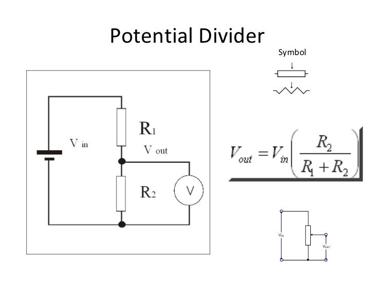
Where R1 represents the battery internal resistance and R2 represents the load resistance.
If R1 remains constant and R2 increases towards infinity, the equation for the p.d. developed across the load shows that
This represents the asymptotic limit as the current falls to zero when the load resistance approaches infinity.
(edited 9 years ago)
Original post by uberteknik
If R1 remains constant and R2 increases towards infinity, the equation for the p.d. developed across the load shows that
This represents the asymptotic limit as the current falls to zero when the load resistance approaches infinity.
If R1 remains constant and R2 increases towards infinity, the equation for the p.d. developed across the load shows that
This represents the asymptotic limit as the current falls to zero when the load resistance approaches infinity.
Nitpickiest nitpick ever: shouldn't that read:
?
Original post by lerjj
Nitpickiest nitpick ever: shouldn't that read:
?
?
Original post by uberteknik
Not the internal resistance (that can be assumed to stay constant). It's the case of when the load resistance approaches infinity.
The current will fall but, more and more p.d. will develop across the increasing load resistance and less will appear across the internal resistance.
The battery can be modelled by a voltage source (E) in series with a resistor (r) representing its internal resistance.
i.e. the battery terminals will then be as shown by the dotted boundary lines in the diagram.
This is identical to a potential divider:
Where R1 represents the battery internal resistance and R2 represents the load resistance.
If R1 remains constant and R2 increases towards infinity, the equation for the p.d. developed across the load shows that
This represents the asymptotic limit as the current falls to zero when the load resistance approaches infinity.
I thought that initially, it's just the wording of the question confused me since it said the terminal p.d. = the voltage across the variable resistor. Could somebody please explain what the question means by that.
I understand that as load resistance approaches infinity, the voltage across the resistor will approach the e.m.f and so terminal p.d.=0. But I just don't understand why it says terminal p.d. = V, that is all.
And thanks!
Original post by Jpw1097
I thought that initially, it's just the wording of the question confused me since it said the terminal p.d. = the voltage across the variable resistor. Could somebody please explain what the question means by that.
Look in the smaller diagram I posted above. Notice the dotted lines showing the outer casing of the cell (battery).
The terminal voltage simply means the voltage appearing at the electrodes (+ve and -ve terminals) of the battery. The question wording means R2 (which is a variable load resistor) is placed across the cell electrodes.
Original post by Jpw1097
I understand that as load resistance approaches infinity, the voltage across the resistor will approach the e.m.f and so terminal p.d.=0. But I just don't understand why it says terminal p.d. = V, that is all.
I understand that as load resistance approaches infinity, the voltage across the resistor will approach the e.m.f and so terminal p.d.=0. But I just don't understand why it says terminal p.d. = V, that is all.
No, the terminal p.d. does not = 0.
The p.d. developed across the internal resistance approaches 0.
The terminal p.d. approaches the e.m.f. of the cell.
Original post by uberteknik
Look in the smaller diagram I posted above. Notice the dotted lines showing the outer casing of the cell (battery).
The terminal voltage simply means the voltage appearing at the electrodes (+ve and -ve terminals) of the battery. The question wording means R2 (which is a variable load resistor) is placed across the cell electrodes.
No, the terminal p.d. does not = 0.
The p.d. developed across the internal resistance approaches 0.
The terminal p.d. approaches the e.m.f. of the cell.
Thanks, that helps a lot!
Quick Reply
Related discussions
- physics alevel edexcel circuit question
- Use a simulator to plot the frequency response of the circuit
- BTEC Applied science Unit 3 2022 Exam
- LDR's in GCSE physics
- need help please!
- Help! Electricity igcse physics qs make no sense
- Question about parallel circuit- OCR AS physics
- Physics Aqa GCSE help
- I don't know what subject to pick
- Things to do in gap years?
- Physics Alevel question :- electromagnetism induction and alternating current
- Edexcel GCSE Physics Paper 2 Higher Tier Triple 1PH0 2H - 16th June 2023 [Exam Chat]
- resistance in a parallel circuit
- Impedance
- Electrical
- URGENT: What equations ARE NOT on the AQA GCSE Physics equation sheet?
- Confusing Capacitor question
- A level physics Electricity question (2)
- Physics A level electricity
- Is Physics A-Level even THAT hard?
Latest
Last reply 1 minute ago
LSE International Social and Public Policy and Economics (LLK1) 2024 ThreadLast reply 4 minutes ago
DWP EO Job Centre Work Coach - March 2024Last reply 4 minutes ago
Official London School of Economics and Political Science 2024 Applicant ThreadPosted 6 minutes ago
Should I insure Warwick or Bristol for EconomicsLast reply 8 minutes ago
TSR Study Together - STEM vs Humanities - Ninth SessionLast reply 8 minutes ago
2024 entry A100 / A101 Medicine fastest and slowest offer sendersMedicine
848
Last reply 8 minutes ago
How can I go from a grade 2 to a grade 8 to 9 in english language paper 2 in daysLast reply 8 minutes ago
Learning basic vocabulary list for Higher Level GCSE in French - is that enough?Last reply 11 minutes ago
Official Cambridge Postgraduate Applicants 2024 Thread