Using Simetrix Pspice For Simple Rectifier Circuit
Hello,
I wonder if I could have some help using this software, I have built a simple circuit which is just an AC voltage source to a transformer then a rectifier, smoothing capacitor and load.
Whenever I attach a ground to the rectifier section and run the circuit I get DCOP failed. I've even tried connecting the ground through a very high resistance but it doesn't make a difference.
I really need to graph the output of the smoothing section, but I'm not getting anywhere with this, I know I need a ground connected for a reference voltage.
Never have this type of problem with a breadboard and real components!
Cheers
Original post by wtaf
Hello,
I wonder if I could have some help using this software, I have built a simple circuit which is just an AC voltage source to a transformer then a rectifier, smoothing capacitor and load.
Whenever I attach a ground to the rectifier section and run the circuit I get DCOP failed. I've even tried connecting the ground through a very high resistance but it doesn't make a difference.
I really need to graph the output of the smoothing section, but I'm not getting anywhere with this, I know I need a ground connected for a reference voltage.
Never have this type of problem with a breadboard and real components!
Cheers
I wonder if I could have some help using this software, I have built a simple circuit which is just an AC voltage source to a transformer then a rectifier, smoothing capacitor and load.
Whenever I attach a ground to the rectifier section and run the circuit I get DCOP failed. I've even tried connecting the ground through a very high resistance but it doesn't make a difference.
I really need to graph the output of the smoothing section, but I'm not getting anywhere with this, I know I need a ground connected for a reference voltage.
Never have this type of problem with a breadboard and real components!
Cheers
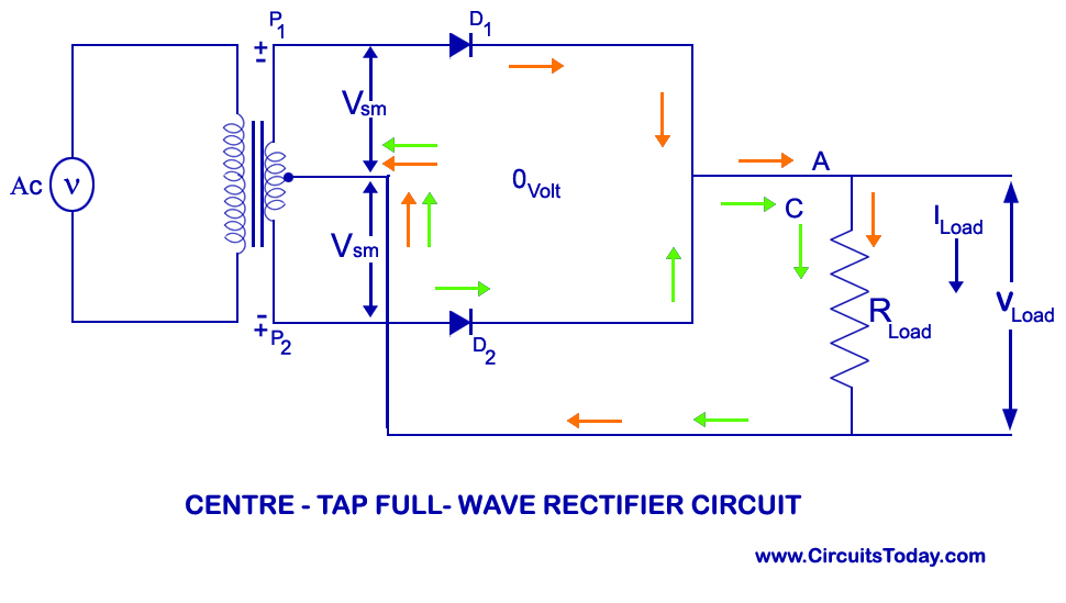
Try splitting the transformer to create an effective centre tap connected to ground, then reference the load to that.
Original post by wtaf
I'd like to add, I downloaded Tina, and was able to use a transformer to step down from 230V to 23V in 5 min.
Problem is this crappy Simetrix software is what I have to use for my assignments, so I'll be hugely grateful if someone can help me with this.
Problem is this crappy Simetrix software is what I have to use for my assignments, so I'll be hugely grateful if someone can help me with this.
If you are referencing the Tx1 probe to gnd, then the 25 Ohms and 1M parallel resistors may be treated like a potential divider by the modelling software. Hence the 40mV or so output.
Try using a differential mode probe hooked across the R1 25 Ohms resistor AC coupled.
Probe|Place FixedDiff. Voltage Probe...
or
Place|Probe|Differential Voltage Probe
(edited 6 years ago)
Original post by uberteknik
If you are referencing the Tx1 probe to gnd, then the 25 Ohms and 1M parallel resistors may be treated like a potential divider by the modelling software. Hence the 40mV or so output.
Try using a differential mode probe hooked across the R1 25 Ohms resistor AC coupled.
Probe|Place FixedDiff. Voltage Probe...
Try using a differential mode probe hooked across the R1 25 Ohms resistor AC coupled.
Probe|Place FixedDiff. Voltage Probe...
Doesn't seem to be working at all mate, all I have now is a 25 ohm load resistor on each winding and it's still giving me the same output. There is no potential divider now.
Original post by wtaf
Doesn't seem to be working at all mate, all I have now is a 25 ohm load resistor on each winding and it's still giving me the same output. There is no potential divider now.
Unfortunately I'm not familiar with the Simetrix version. It uses the generic PSPICE math' models produced by Berkley University but with it's own User Interface. Without having a good play with the package in front of me, I'm just stabbing in the dark.

Original post by uberteknik
Unfortunately I'm not familiar with the Simetrix version. It uses the generic PSPICE math' models produced by Berkley University but with it's own User Interface. Without having a good play with the package in front of me, I'm just stabbing in the dark.
Thanks for trying to help me out mate, I've asked my tutor but he says he's very busy just now and will get back to me when he has time. So i'm in study limbo just now.
If you're interested the software is free to download, but I'm not impressed with it one bit.
Original post by wtaf
Thanks for trying to help me out mate, I've asked my tutor but he says he's very busy just now and will get back to me when he has time. So i'm in study limbo just now.
If you're interested the software is free to download, but I'm not impressed with it one bit.
If you're interested the software is free to download, but I'm not impressed with it one bit.
I might take a look a bit later.
Hi uber,
Just to let you know I got to the bottom of this stupid thing. There is a fault with the simulation. Instead of using the "ideal transformer", I used an "ideal dc transformer" in the exact same circuit - straight away it works and it collaborates with the calculations I have been doing. I should have thought something was wrong when I found the wave being transformed into a cosine, that was very weird.
So, to sum - don't trust simulations 100%
Original post by wtaf
Hi uber,
Just to let you know I got to the bottom of this stupid thing. There is a fault with the simulation. Instead of using the "ideal transformer", I used an "ideal dc transformer" in the exact same circuit - straight away it works and it collaborates with the calculations I have been doing. I should have thought something was wrong when I found the wave being transformed into a cosine, that was very weird.
So, to sum - don't trust simulations 100%
Just to let you know I got to the bottom of this stupid thing. There is a fault with the simulation. Instead of using the "ideal transformer", I used an "ideal dc transformer" in the exact same circuit - straight away it works and it collaborates with the calculations I have been doing. I should have thought something was wrong when I found the wave being transformed into a cosine, that was very weird.
So, to sum - don't trust simulations 100%
It had to be something simple. lol. I was thinking along the lines of a d.c. problem earlier when I said try the AC coupling probe.
That's good to hear though. Engineering is 1% inspiration and 99% frustration as you will discover on many more occasions. Still it's all part of becoming an engineer, building that experience to expert level and learning the quirks of simulation tools!
Spoiler
(edited 6 years ago)
Quick Reply
Related discussions
- How to find the equivalent resistance of this circuit?
- HNC electrical principles
- HNC MATHS A2 Task 3 (Radio Transmitters)
- Electricity - Calculating currents & Voltages etc
- Drift Velocity Q
- Multisum circuit
- worst university..
- Engineering maths help
- L4 Apple Apprenticeship DevOps/Software Engineering
- Design your own F1 Track!
- electrical schematics and analyzing signals
- Capacitor Question (PHYS)
- Isaac Physics.
- Use a simulator to produce a resonance curve between 800 Hz and 4.5 kH
- Superposition theorem problem
- Experience of using Circuit Laundry at Uni of Notts?
- Electrical
- Resistance of the LDR
- HNC Electrical engineering
- physics alevel edexcel circuit question