physics ocr unit 2 help
When working out internal resistance, you increase the resistance of the variable resistor and this increases voltage as the share between it and the internal resistane is higher. Apparently "The current decreases becuase the resistance is higher", i really dont get this bit because i=v/r and since v is higher and r lower shouldnt I be the same.
Also coming to potential dividers, when you increase the resistance of a component why does its voltage increase, i understand the reason is because current is constant and therefore the coltage sher must change but then doent that contradict the previous concept of what an increase in resistance does.
Can someone help please because right now physics is one big mess when it comes to this.
Original post by dany_boy
When working out internal resistance, you increase the resistance of the variable resistor and this increases voltage as the share between it and the internal resistane is higher. Apparently "The current decreases becuase the resistance is higher", i really dont get this bit because i=v/r and since v is higher and r lower shouldnt I be the same.
Also coming to potential dividers, when you increase the resistance of a component why does its voltage increase, i understand the reason is because current is constant and therefore the coltage sher must change but then doent that contradict the previous concept of what an increase in resistance does.
Can someone help please because right now physics is one big mess when it comes to this.
Also coming to potential dividers, when you increase the resistance of a component why does its voltage increase, i understand the reason is because current is constant and therefore the coltage sher must change but then doent that contradict the previous concept of what an increase in resistance does.
Can someone help please because right now physics is one big mess when it comes to this.
Just imagine internal resistance is just another tiny resistor in series with the variable resistor, the only difference is that this resistor is 'inside' the battery.
So if you increased the resistance of the variable resistor, the total resistance of the circuit would increase. The emf of the cell is constant so according to I=V/R, the current will decrease.
About the potential divider. Voltage is 'energy dropped' across the resistance. So if you increased the resistance, then more 'energy' would be needed to push the current through. This mean voltage across this resistance has increased. The current still decreases as you would expect when increasing the resistance though so no contradiction here

(edited 8 years ago)
Thanks a lot for your response, you cleared this up a lot more but i do have have querstion about what you said.
Firstly, when using I=V/R, i agree with the fact that emf is constant but since your applying it to the variable resistor should you look at the voltage the variable resistor as.
Also, if i increased the resistance of a component of a potential divider, does that mean that the curent of the circuit as a whole would be lower.
once again thanks and apoligise for all the typing mistakes yesterday, i was pretty tired
Original post by NDVA
So if you increased the resistance of the variable resistor, the total resistance of the circuit would increase. The emf of the cell is constant so according to I=V/R, the current will decrease.
About the potential divider. Voltage is 'energy dropped' across the resistance. So if you increased the resistance, then more 'energy' would be needed to push the current through. This mean voltage across this resistance has increased. The current still decreases as you would expect when increasing the resistance though so no contradiction here
Firstly, when using I=V/R, i agree with the fact that emf is constant but since your applying it to the variable resistor should you look at the voltage the variable resistor as.
Also, if i increased the resistance of a component of a potential divider, does that mean that the curent of the circuit as a whole would be lower.
once again thanks and apoligise for all the typing mistakes yesterday, i was pretty tired
Original post by dany_boy
Firstly, when using I=V/R, i agree with the fact that emf is constant but since your applying it to the variable resistor should you look at the voltage the variable resistor as.
Firstly, when using I=V/R, i agree with the fact that emf is constant but since your applying it to the variable resistor should you look at the voltage the variable resistor as.
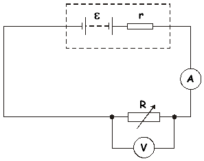
We apply I=V/R to the whole circuit in this case, that is why the current will decrease. Have a look at this picture
Original post by dany_boy
Also, if i increased the resistance of a component of a potential divider, does that mean that the curent of the circuit as a whole would be lower.
Yes, the current would be lower because you increase the resistance of the whole circuit. However, this decrease is to a smaller extent than the increase in the resistance of component resistor (the current depends on both resistors), so the voltage drops across that resistor will increase.
(edited 8 years ago)
Original post by NDVA
We apply I=V/R to the whole circuit in this case, that is why the current will decrease. Have a look at this picture

Thanks, again
, i understand the p.d stuff now but for the variable resistor stuffi have a question.
As we change the variable resistor, we mesure the current and voltage aroundthe variable resistor. Like this right?
 If this is the case dont we want to use V as the voltage of the resistor?, i dont get why we just know the V is the emf. Also if i did use V=IR on the variable resistorwhat would the value of current be for.
Original post by dany_boy
Thanks, again , i understand the p.d stuff now but for the variable resistor stuff
i have a question.
As we change the variable resistor, we mesure the current and voltage aroundthe variable resistor. Like this right?If this is the case dont we want to use V as the voltage of the resistor?, i dont get why we just know the V is the emf. Also if i did use V=IR on the variable resistorwhat would the value of current be for.
, i understand the p.d stuff now but for the variable resistor stuffi have a question.
As we change the variable resistor, we mesure the current and voltage aroundthe variable resistor. Like this right?
If this is the case dont we want to use V as the voltage of the resistor?, i dont get why we just know the V is the emf. Also if i did use V=IR on the variable resistorwhat would the value of current be for.In this case, the ammeter measures the current in the whole circuit (which is also the current passing through the variable resistor, as two resistors R and r are in series). So with is the total resistance of the circuit
Now we have the current in the circuit. The voltage across the variable resistor will be and this is the value you would get on the voltmeter.
Original post by NDVA
We apply I=V/R to the whole circuit in this case, that is why the current will decrease. Have a look at this picture
Yes, the current would be lower because you increase the resistance of the whole circuit. However, this decrease is to a smaller extent than the increase in the resistance of component resistor (the current depends on both resistors), so the voltage drops across that resistor will increase.
Yes, the current would be lower because you increase the resistance of the whole circuit. However, this decrease is to a smaller extent than the increase in the resistance of component resistor (the current depends on both resistors), so the voltage drops across that resistor will increase.
Thank YOUUUUUUU!!!!
So basically:
Resistance of the variable resistor increases its voltageshare between it and the internal resister increases. Just like in a normalpotential divider. Because the overall resistance is higher and the emf constant,the overall current (same throughout the variable resistor and battery ) willdecrease. When it comes to the potential divider, an increase inresistance means an increase in voltage just like before so the current decreases.But say if the voltage doubled, the current doesn’t decreases by double becausethe current is always determined by the total resistance which the othercomponent has a part of.

Original post by dany_boy
Im right, right? 
Yes

Original post by NDVA
Yes
Thanks a lot, owe you mate. If you ever need help with physics, which you probably wont, you can ask me. (Althought i wouldnt recommend it because it seems im evidently bad, at electricity atleast)
Original post by dany_boy
Thanks a lot, owe you mate. If you ever need help with physics, which you probably wont, you can ask me. (Althought i wouldnt recommend it because it seems im evidently bad, at electricity atleast)
No worries mate
I was really confused the first time I studied about this stuff as well, so I'm glad that I could help you Good luck with your exams!Original post by NDVA
No worries mate I was really confused the first time I studied about this stuff as well, so I'm glad that I could help you Good luck with your exams!
I was really confused the first time I studied about this stuff as well, so I'm glad that I could help you Good luck with your exams!Hi, its me again, im going to start doing past papers and i needed a word of advice and a little help. From now on when i look at a circuit, should i try to detemine the current of the circuit by looking at the net resistance and voltage.
I mean last time, with all that variable resisotor stuff, i kept on getting confused because i thought if i considered just that resistor i would be able to see the fact that current decrease which i couldnt. And from what you pretty much taught me, you cant really look at one component and find the resisance.
So i guess my question is when can i look at one component to find the current, and whats the exception?
Original post by dany_boy
Hi, its me again, im going to start doing past papers and i needed a word of advice and a little help. From now on when i look at a circuit, should i try to detemine the current of the circuit by looking at the net resistance and voltage.
I mean last time, with all that variable resisotor stuff, i kept on getting confused because i thought if i considered just that resistor i would be able to see the fact that current decrease which i couldnt. And from what you pretty much taught me, you cant really look at one component and find the resisance.
So i guess my question is when can i look at one component to find the current, and whats the exception?
I don't think there is a general way to solve problems involving circuits. However, my advice is that when we use , we should ask ourselves 'which V,I,R are we dealing with here?'. Also, remember that resistors in series would have the same current passing through, while resistors in parallel would have the same voltage drop across them.
Let's take this circuit as an example:
Say, we want to find the current in this circuit. We notice that current passing through would be equal to total current passing through and , as is in series with the system. Hence:
Now that we have , we can calculate
From this, we can calculate voltage across the system by using:
as and are in series.
Now we notice and are parallel with each other. This means:
From this we can calculate the current in each branch:
(It would be no surprise that as and are in series)
(edited 8 years ago)
Quick Reply
Related discussions
- A-level Exam Discussions 2024
- GCSE Exam Discussions 2024
- A Level Exam Discussions 2023
- GCSE Exam Discussions 2023
- AS/A Level Chemistry Study Group 2023/2024
- GCSE Computer Science help
- GCSE 2023 Grade Boundaries (All Exam Boards)
- GCSE Biology Study Group 2022-2023
- Health and social care unit 4
- A-level Physics Study Group 2022-2023
- A Level Advice
- Health and social care alevel- whats my overall
- OCR A A-level Physics Paper 1 Modelling Physics (H556/01) - 24th May 2024 [Exam Chat]
- Economic's AS + A2 Notes (ALL BOARDS)
- A Level Physics OCR B : Where to start?
- About gcse pe and sports studies btec both ocr
- OCR GCSE Physics A Paper 4 Higher Tier (J249/04) - 16th June 2023 [Exam Chat]
- UCAS application What is my qualification called for OCR media
- A-level History Study Group 2022-2023
- How to get A/A* in A level chemistry
Latest
Trending
Last reply 1 day ago
Edexcel A Level Politics Paper 1 (9PL0 01) - 21st May 2024 [Exam Chat]A-levels
10
Trending
Last reply 1 day ago
Edexcel A Level Politics Paper 1 (9PL0 01) - 21st May 2024 [Exam Chat]A-levels
10